The D Latch
Since the enable input on a gated S-R latch provides a way to latch the Q and not-Q outputs without regard to the status of S or R, we can eliminate one of those inputs to create a multivibrator latch circuit with no “illegal” input states.
Such a circuit is called a D latch, and its internal logic looks like this:
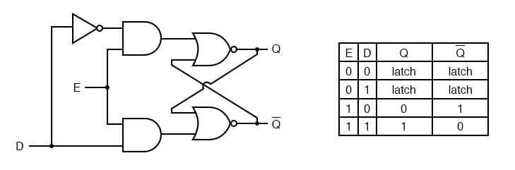
Note that the R input has been replaced with the complement (inversion) of the old S input, and the S input has been renamed to D. As with the gated S-R latch, the D latch will not respond to a signal input if the enable input is 0—it simply stays latched in its last state. When the enable input is 1, however, the Q output follows the D input.
Since the R input of the S-R circuitry has been done away with, this latch has no “invalid” or “illegal” state. Q and not-Q are always opposite of one another.
If the above diagram is confusing at all, the next diagram should make the concept simpler:
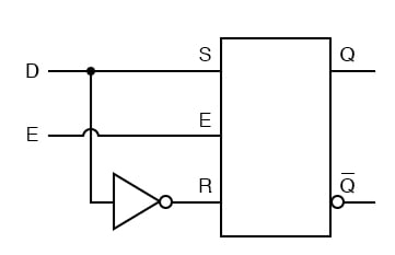
Like both the S-R and gated S-R latches, the D latch circuit may be found as its own prepackaged circuit, complete with a standard symbol:

The D latch is nothing more than a gated S-R latch with an inverter added to make R the complement (inverse) of S.
Let’s explore the ladder logic equivalent of a D latch, modified from the basic ladder diagram of an S-R latch:

An application for the D latch is a 1-bit memory circuit. You can “write” (store) a 0 or 1 bit in this latch circuit by making the enable input high (1) and setting D to whatever you want the stored bit to be. When the enable input is made low (0), the latch ignores the status of the D input and merrily holds the stored bit value, outputting at the stored value at Q, and its inverse on output not-Q.
REVIEW:
- A D latch is like an S-R latch with only one input: the “D” input. Activating the D input sets the circuit, and de-activating the D input resets the circuit. Of course, this is only if the enable input (E) is activated as well. Otherwise, the output(s) will be latched, unresponsive to the state of the D input.
- D latches can be used as 1-bit memory circuits, storing either a “high” or a “low” state when disabled, and “reading” new data from the D input when enabled.