Ring Counter in Digital Logic
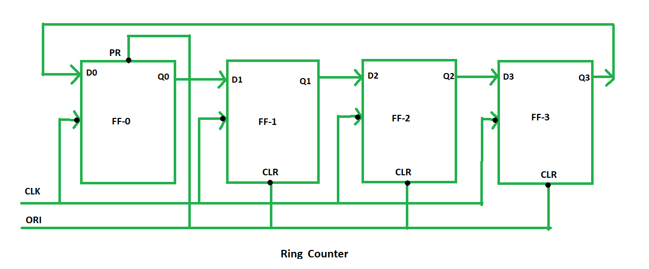
A ring counter is a typical application of the Shift register. The ring counter is almost the same as the shift counter. The only change is that the output of the last flip-flop is connected to the input of the first flip-flop in the case of the ring counter but in the case of the shift resister it is taken as output. Except for this, all the other things are the same.
No. of states in Ring counter = No. of flip-flop used
So, for designing a 4-bit Ring counter we need 4 flip-flops.  In this diagram, we can see that the clock pulse (CLK) is applied to all the flip-flops simultaneously. Therefore, it is a Synchronous Counter. Also, here we use Overriding input (ORI) for each flip-flop. Preset (PR) and Clear (CLR) are used as ORI. When PR is 0, then the output is 1. And when CLR is 0, then the output is 0. Both PR and CLR are active low signal that always works in value 0.
PR = 0, Q = 1
CLR = 0, Q = 0
These two values are always fixed. They are independent of the value of input D and the Clock pulse (CLK). Working – Here, ORI is connected to Preset (PR) in FF-0 and it is connected to Clear (CLR) in FF-1, FF-2, and FF-3. Thus, output Q = 1 is generated at FF-0, and the rest of the flip-flop generates output Q = 0. This output Q = 1 at FF-0 is known as Pre-set 1 which is used to form the ring in the Ring Counter. 
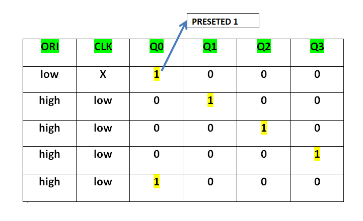
This Preseted 1 is generated by making ORI low and that time Clock (CLK) becomes don’t care. After that ORI is made to high and apply low clock pulse signal as the Clock (CLK) is negative edge triggered. After that, at each clock pulse, the preseted 1 is shifted to the next flip-flop and thus forms a Ring. From the above table, we can say that there are 4 states in a 4-bit Ring Counter.
4 states are:
  1 0 0 0
  0 1 0 0
  0 0 1 0
  0 0 0 1
In this way can design a 4-bit Ring Counter using four D flip-flops.
Types of Ring Counter: There are two types of Ring Counter:
- Straight Ring Counter: It is also known as One hot Counter. In this counter, the output of the last flip-flop is connected to the input of the first flip-flop. The main point of this Counter is that it circulates a single one (or zero) bit around the ring.
 Here, we use Preset (PR) in the first flip-flop and Clock (CLK) for the last three flip-flops.
 - Twisted Ring Counter – It is also known as a switch-tail ring counter, walking ring counter, or Johnson counter. It connects the complement of the output of the last shift register to the input of the first register and circulates a stream of ones followed by zeros around the ring.
 Here, we use Clock (CLK) for all the flip-flops. In the Twisted Ring Counter, the number of states = 2 X the number of flip-flops.
What is a Ring Counter : Working, Classification & Applications
Counters are sequential circuits whose function is to count pulse, frequency and time of the signal using a single clock signal. It is an important component of digital electronics since entire electronic devices work on counters. They are designed by grouping a (similar or different) set of flipflops. Counters operate in different modes of modules, which are represented by the number of states of the cycle. There are two types of counters, they are synchronous and asynchronous counter. The synchronous counter operates based on the input clock signal and the asynchronous counter is independent of the input clock signal. The synchronous counter is a shift register counter which is further classified as a ring-type and twisted type ring counter.
___________________________________________________________


