_________________________________________________________________________________
______________________________
Arvind Upadhyay is an entrepreneur, bestselling author, philanthropist and the world’s best Life and Business Strategist. Author of 60+ internationally bestselling books, Arvind Upadhyay has empowered more than 40 million people from 50 + countries through his audio, video and life training programs. He created the #1 personal and professional development program of all time, and more than 2 million people have attended his live seminars.
__________________________________________________________________________
It is branch of engineering which deals with various types of instrument to record, monitor, indicate and control various physical parameters such as pressure, temperature, etc.
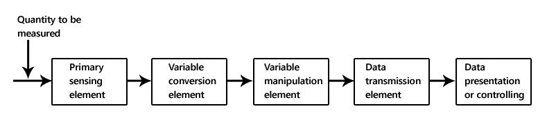
Block diagram of instrumentation system
The block diagram shown above is of basic instrumentation system. It consist of primary sensing element, variable manipulation element, data transmission element and data presentation element.
Primary sensing element
The primary sensing element is also known as sensor. Basically transducers are used as a primary sensing element. Here, the physical quantity (such as temperature, pressure etc.) are sensed and then converted into analogues signal.
Variable conversion element
It converts the output of primary sensing element into suitable form without changing information. Basically these are secondary transducers.
Variable manipulation element
The output of transducer may be electrical signal i.e. voltage, current or other electrical parameter. Here, manipulation means change in numerical value of signal. This element is used to convert the signal into suitable range.
Data transmission element
Sometimes it is not possible to give direct read out of the quality at a particular place (Example – Measurement of temperature in the furnace). In such a case, the data should transfer from one place to another place through channel which is known as data transmission element. Typically transmission path are pneumatic pipe, electrical cable and radio links. When radio link is used, the electronic instrumentation system is called as telemetry system.
Data presentation or controlling element
Finally the output is recorded or given to the controller to perform action. It performs different functions like indicating, recording or controlling.
Block Diagram -
The blocks are drawn in the form of squares or rectangles connected by single lines with arrowheads at the terminal end, showing the direction of the signal path from input to output. Normally, the necessary information to describe the stages of components is contained in the blocks.

An electronics instrumentation system generally consists of the following three constituents:
- Input unit.
- Signal conditioning or processing unit and
- Output unit.
Figure 1 gives the block diagram of an analog instrumentation system.
Input Unit (Transducer): The input unit receives the quantity under measurement and converts it into proportional incremental electrical signal such as voltage, current, magnetic flux, frequency or phase angle of an ac voltage, increment in resistance, capacitance or inductance. The electrical signal so produced is fed to the next unit namely signal processing unit.
he Signal Processing Unit: The electrical signal produced by the input unit or the transducer is, in general, very weak. It is, therefore amplified. In addition, it may be filtered and modified into a form acceptable to the output unit. Thus, signal processing may include one or all of these functions: amplification, filtering and modification of form. Quite often the signal processing unit forms an integral part of the input unit.

The Output Unit: The output unit measures the output of the signal processing unit and may be in the form of
- Indicating Instrument
- A CRO or a chart recorder for visual display
- Magnetic tape recorder for temporary or permanent storage of the input data
- A digital computer for data manipulation or process control.
Thus, the complete instrumentation system may assume various forms depending on what is to be measured and how the output is to be presented.
Digital Instrumentation System
It may include some or all the elements shown in figure 2. The basic functional operations within a digital system include handling analog signals, making the measurements, converting and handling digital data and internal programming and control. The function of each of the system elements of figure 2 is given below:

Transducer: It translate the physical parameter such as temperature, pressure, displacement, velocity, acceleration etc. into suitable electrical signal. Electrical quantity such as voltage, current, resistance, frequency also may be measured directly.
Signal Conditioner: It include the supporting circuitry for the transducer. The circuitry may provide excitation power, balancing circuits, calibrating elements. A typical example of signal conditioner is a strain gauge bridge balance and power supply unit.
Scanner or Multiplexer: It accept multiple analog inputs and sequentially connects them to one measuring instrument.
Signal Converter: It translates the analog signal to a form acceptable by the analog-to-digital (A/D) converter.
Analog-to-Digital (A/D) Converter: It converts the analog signal to its equivalent digital form. The output of A/D converter may be displayed visually and is also made available as voltage output in discrete steps for further processing or recording on a digital recorder.
Auxiliary Equipment: This includes instruments for system programming functions and digital data processing. Typical auxiliary functions include linearizing and limit comparison. All these functions may be performed by individual instruments or by a digital computer.
Digital Recorder: It records digital signals on magnetic tape, hard disk, pen drive, SD card etc. or a combination of these systems.
_______________________________________________________________________